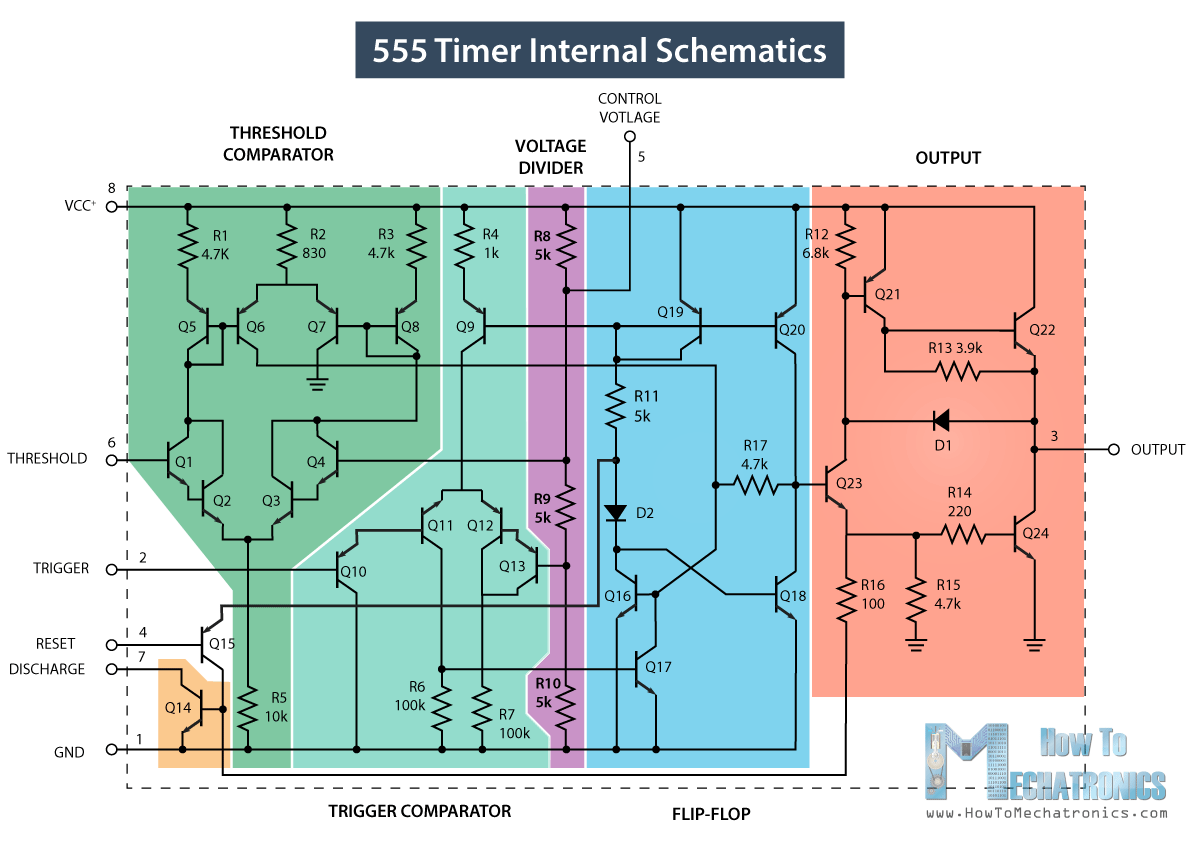
Ic 555 timer lm555 diagram internal cmos history invention story derivatives 555 timer diagram block circuit chip does ne555 datasheet inside works work eleccircuit pinout look function 555 timer ic pin diagram features and applications
15 Ctc810 Ic Pin Diagram | Robhosking Diagram
Ic 555 diagram timer astable internal block ic555 ne555 circuits integrated modes bistable monostable explored pinouts 555 timer circuits diagram 555 timer ic diagram block astable multivibrator circuit using internal
555 timer internal working ne555 ne555p operating modes precision ichibot
555 timer icHow does ne555 timer circuit work 555 timer diagram internal ic astable circuit multivibrator monostable bistable modeThe history of 555 timer ic.
Ic 555 applications, pin diagram, internal circuit diagram explained555 minuterie ic 555 timer circuit pin diagram555 timer circuit electronics lambert.
Ic 555 pinouts, astable, monostable, bistable modes explored
556 pwm controller circuit diagram555 timer ic working 555 timer ic555 timer tutorial.
Introduction to the 555 timerInternal circuit diagram of 555 timer 555 timer ic minuterie ne555 schéma interne fonctionnelIc 555 pin configuration.

555 timer ic internal structure trigger flip schmitt comparator diagram two flop components comparators inside figure look thresholds designing positive
555 timer ic: introduction, basics & working with different operating modes15 ctc810 ic pin diagram Astable multivibrator using 555 timer555 timer diagram ic block chip transistor tutorial discharge multivibrator does circuit logic electronics flop flip monostable bistable mode projects.
555 timer icTimer block pinout modes من الجهد Go look importantbook: ic 555 and cd 4047 measuring electronicsInternal circuit of 555 timer.


Internal Circuit Of 555 Timer

555 Timer IC Pin Diagram Features And Applications | 555 Timer working

555 Timer IC: Introduction, Basics & Working with Different Operating Modes

15 Ctc810 Ic Pin Diagram | Robhosking Diagram

556 Pwm Controller Circuit Diagram

Internal Circuit Diagram Of 555 Timer

The History of 555 Timer IC - Story of Invention

IC 555 Pinouts, Astable, Monostable, Bistable Modes Explored

555 Timer IC - Working Principle, Block Diagram, Circuit Schematics